
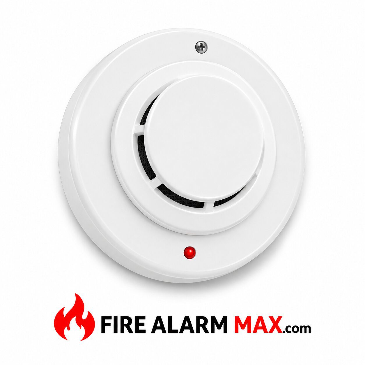
System Sensor 2151 Conventional Optical Fire Detector Head
The System Sensor 2151 is a low-profile conventional optical fire detector head designed for compatible fire alarm systems. It uses advanced light-scattering technology to monitor airborne combustion particles and provide an alarm response through an approved mounting base and control panel.
Additionally, the detector features dual LED indicators, magnetic functional testing, and remote alarm annunciation capability. Furthermore, its removable sensing chamber screen and plug-in mounting design support professional maintenance.
Therefore, the System Sensor 2151 provides a practical optical detection solution for approved indoor fire protection applications.
Advanced Optical Fire Detection Technology
The System Sensor 2151 incorporates a specially designed optical sensing chamber.
During normal operation, the detector monitors the chamber for changes associated with airborne combustion particles.
When particles enter the sensing area, they scatter light toward the optical receiver.
As a result, the sensing electronics recognize a change in the chamber’s optical response.
Additionally, the detector uses integrated signal-processing circuitry to help reduce certain nuisance alarms.
Therefore, the 2151 can provide dependable optical detection when installed and maintained correctly.
However, its performance depends on environmental conditions and compatible system equipment.
Optical-Only Detection Design
The 2151 uses optical sensing without an integrated thermal detector.
Unlike the 2151T model, it does not include a 135°F fixed-temperature heat sensor.
Additionally, it does not incorporate carbon monoxide sensing or ionization technology.
As a result, its primary detection function is based on airborne combustion particles.
Furthermore, this distinction is important when replacing equipment in an existing fire alarm installation.
Therefore, technicians must verify that the approved system design specifies the optical-only 2151.
Response to Developing Fire Conditions
The optical sensing chamber is designed to respond to particles produced by a range of combustion sources.
For example, slowly developing fires can release airborne particles before substantial heat develops.
Additionally, certain electrical equipment faults may produce detectable combustion products.
As a result, the detector can recognize conditions associated with developing fires.
However, optical sensing performance varies with particle characteristics, airflow, and environmental conditions.
Therefore, technicians should select detector locations according to the approved fire protection design.
Conventional Fire Alarm Operation
The System Sensor 2151 is a conventional detector head.
Unlike an intelligent addressable detector, it does not independently communicate a unique digital device address.
Instead, it operates through a compatible mounting base connected to an approved initiating device circuit.
Additionally, the selected base determines the applicable wiring and electrical requirements.
For example, a two-wire base provides a different circuit arrangement from a four-wire relay base.
Consequently, the detector should not be connected to an incompatible fire alarm panel.
Multiple Mounting Base Options
The 2151 supports several manufacturer-approved plug-in mounting bases.
For example, the B110LP provides a conventional two-wire installation arrangement.
Meanwhile, the B112LP provides a four-wire configuration with relay contacts.
Additionally, the B114LP and B116LP families support other approved circuit arrangements.
As a result, the same detector head can serve different compatible applications.
However, the operating voltage and alarm current depend on the selected base.
Therefore, installers must consult the exact base installation manual.
Dual LED Status Indicators
The System Sensor 2151 includes two LED indicators positioned for 360-degree visibility.
During normal standby operation, the LEDs flash periodically to indicate that the detector is receiving power and operating.
When the detector enters an alarm condition, the LEDs latch on.
As a result, technicians can identify the activated detector during inspection.
Additionally, the visible indicators assist with routine system maintenance.
However, LED operation alone does not establish that the complete fire alarm system is functional.
Therefore, technicians must verify the control panel response during testing.
Magnetic Functional Testing
The detector includes an internal magnetic test feature.
First, qualified technicians place the approved test magnet at the designated location on the housing.
Next, the detector activates its test response.
Additionally, the alarm LEDs should latch on and the connected control panel should register the alarm.
As a result, technicians can verify important electronic and signaling functions.
However, magnetic testing does not replace every required sensing chamber test.
Therefore, maintenance personnel should also follow the manufacturer’s approved smoke-entry testing procedures.
Remote Alarm Indication
The 2151 supports remote alarm indication through compatible mounting bases.
For example, the manufacturer identifies the RA400Z remote annunciator as an available accessory.
Additionally, remote indication can help personnel identify an activated detector in a concealed or difficult-to-view location.
As a result, approved installations can provide alarm information at a more accessible location.
However, the remote annunciator requires the correct wiring arrangement.
Therefore, technicians must confirm compatibility with the selected base.
Key Features
Low-Current Electrical Operation
The System Sensor 2151 has a published operating voltage range of 8.5 to 35 VDC.
Additionally, the manufacturer specifies a maximum standby current of 120 microamps.
As a result, the detector supports low-current conventional fire alarm operation.
However, the electrical requirements of the complete detector assembly depend on the selected base.
For example, a relay-equipped four-wire base has different alarm current characteristics from a two-wire base.
Therefore, technicians must calculate circuit loading using the appropriate base documentation.
Alarm Latching and Reset
The detector provides a latching alarm response.
During an alarm condition, its LED indicators remain illuminated until the system is reset.
Additionally, the manufacturer specifies reset by momentary interruption of operating power.
As a result, the compatible control panel can restore the detector after an approved reset procedure.
However, the underlying alarm condition must be investigated before resetting the system.
Therefore, technicians should follow the facility’s established fire alarm procedures.
Low-Profile Detector Construction
The 2151 features a compact plug-in housing.
Additionally, the manufacturer documents a height of approximately 2.0 inches when installed in the B401 base.
The overall diameter depends on the selected mounting base.
For example, the B401 assembly has a published diameter of approximately 4.1 inches.
Meanwhile, the B110LP assembly has a published diameter of approximately 6.1 inches.
Therefore, buyers should distinguish detector-head dimensions from complete installed assembly dimensions.
Removable Sensing Chamber Screen
The 2151 includes a removable chamber screen.
Additionally, the chamber construction helps limit the entry of dirt and insects.
As a result, the sensing assembly can be maintained using the manufacturer’s approved procedures.
Furthermore, the removable screen supports periodic cleaning.
However, contamination can still affect detector sensitivity.
Therefore, qualified technicians should inspect and clean the detector at the required intervals.
Environmental Operating Requirements
The System Sensor 2151 operates in ambient temperatures from 32°F to 120°F (0°C to 49°C).
Additionally, the manufacturer specifies relative humidity from 10% to 93%, non-condensing.
As a result, the detector is intended for suitable indoor environments.
However, excessive moisture, dust, or unsuitable airflow can affect performance.
Therefore, technicians must evaluate the installation conditions before selecting the location.
Furthermore, the detector’s operating temperature range differs from that of the 2151T.
Airflow and Special Applications
The 2151 optical sensing platform is also documented for certain air-handling applications.
Specifically, System Sensor identifies approved configurations using the B114LP or B114LPBT base.
Additionally, the manufacturer’s special-applications literature identifies airflow capability up to 3,000 feet per minute for those configurations.
However, the detector head alone is not a complete duct detection assembly.
Therefore, technicians must verify the exact base, installation method, and applicable approval before using it in an air-handling system.
Typical Applications
The System Sensor 2151 supports approved conventional fire alarm installations.
For example, suitable applications may include offices, commercial properties, institutional buildings, and other protected indoor areas.
Additionally, its low-profile construction supports ceiling-mounted installations.
Furthermore, the availability of different mounting bases provides flexibility for approved replacement projects.
However, the detector must be compatible with the installed fire alarm control panel.
Therefore, installers should verify the approved system configuration before ordering.
Installation and Compatibility
Before installation, technicians should identify the exact detector model and compatible mounting base.
Next, they should verify the fire alarm control panel and initiating circuit requirements.
Additionally, installers must inspect the detector contacts, housing, and sensing chamber.
The detector head should be installed using the manufacturer’s approved plug-in procedure.
Afterward, qualified personnel must verify alarm activation and reset.
Therefore, the detector should enter service only after successful commissioning and functional testing.
Maintenance and Functional Testing
Regular maintenance helps preserve dependable optical detection.
First, technicians should inspect the housing and chamber screen for contamination.
Next, they should verify the electrical contacts and mounting arrangement.
Additionally, they should perform the approved magnetic test.
Furthermore, they should conduct required smoke-entry and sensitivity testing according to applicable procedures.
However, an electronic test alone does not confirm every aspect of detector performance.
Consequently, technicians must follow the complete maintenance requirements.
Important Replacement Considerations
The 2151 is a specific conventional optical detector head.
Additionally, the related 2151T incorporates an independent fixed-temperature thermal sensing function.
As a result, the two models have different detection characteristics.
Furthermore, the 2151A and 2151E are separate regional variants.
However, physical similarity does not establish interchangeability.
Therefore, technicians must confirm the exact model, mounting base, control panel compatibility, and certification requirements.
Conclusion
Overall, the System Sensor 2151 provides conventional optical fire detection for compatible fire alarm systems.
Additionally, its dual LEDs, magnetic test feature, removable chamber screen, and low-current operation support professional maintenance.
Furthermore, its compatibility with multiple approved mounting bases provides installation flexibility.
Therefore, the 2151 remains a practical component for approved installations when its condition, mounting base, control panel compatibility, and safety requirements have been verified.
| Weight | 2 lbs |
|---|---|
| Dimensions | 5 × 5 × 5 in |
| Brand |
Your Payment information is processed securely. We do not store credit card details, nor have access to your credit card information.
Orders ship same day
Thousands of parts in stock
Reliable products & service
Order anytime, anywhere
System Sensor 2151 Conventional Optical Fire Detector Head
The System Sensor 2151 is a low-profile conventional optical fire detector head designed for compatible fire alarm systems. It uses advanced light-scattering technology to monitor airborne combustion particles and provide an alarm response through an approved mounting base and control panel.
Additionally, the detector features dual LED indicators, magnetic functional testing, and remote alarm annunciation capability. Furthermore, its removable sensing chamber screen and plug-in mounting design support professional maintenance.
Therefore, the System Sensor 2151 provides a practical optical detection solution for approved indoor fire protection applications.
Advanced Optical Fire Detection Technology
The System Sensor 2151 incorporates a specially designed optical sensing chamber.
During normal operation, the detector monitors the chamber for changes associated with airborne combustion particles.
When particles enter the sensing area, they scatter light toward the optical receiver.
As a result, the sensing electronics recognize a change in the chamber’s optical response.
Additionally, the detector uses integrated signal-processing circuitry to help reduce certain nuisance alarms.
Therefore, the 2151 can provide dependable optical detection when installed and maintained correctly.
However, its performance depends on environmental conditions and compatible system equipment.
Optical-Only Detection Design
The 2151 uses optical sensing without an integrated thermal detector.
Unlike the 2151T model, it does not include a 135°F fixed-temperature heat sensor.
Additionally, it does not incorporate carbon monoxide sensing or ionization technology.
As a result, its primary detection function is based on airborne combustion particles.
Furthermore, this distinction is important when replacing equipment in an existing fire alarm installation.
Therefore, technicians must verify that the approved system design specifies the optical-only 2151.
Response to Developing Fire Conditions
The optical sensing chamber is designed to respond to particles produced by a range of combustion sources.
For example, slowly developing fires can release airborne particles before substantial heat develops.
Additionally, certain electrical equipment faults may produce detectable combustion products.
As a result, the detector can recognize conditions associated with developing fires.
However, optical sensing performance varies with particle characteristics, airflow, and environmental conditions.
Therefore, technicians should select detector locations according to the approved fire protection design.
Conventional Fire Alarm Operation
The System Sensor 2151 is a conventional detector head.
Unlike an intelligent addressable detector, it does not independently communicate a unique digital device address.
Instead, it operates through a compatible mounting base connected to an approved initiating device circuit.
Additionally, the selected base determines the applicable wiring and electrical requirements.
For example, a two-wire base provides a different circuit arrangement from a four-wire relay base.
Consequently, the detector should not be connected to an incompatible fire alarm panel.
Multiple Mounting Base Options
The 2151 supports several manufacturer-approved plug-in mounting bases.
For example, the B110LP provides a conventional two-wire installation arrangement.
Meanwhile, the B112LP provides a four-wire configuration with relay contacts.
Additionally, the B114LP and B116LP families support other approved circuit arrangements.
As a result, the same detector head can serve different compatible applications.
However, the operating voltage and alarm current depend on the selected base.
Therefore, installers must consult the exact base installation manual.
Dual LED Status Indicators
The System Sensor 2151 includes two LED indicators positioned for 360-degree visibility.
During normal standby operation, the LEDs flash periodically to indicate that the detector is receiving power and operating.
When the detector enters an alarm condition, the LEDs latch on.
As a result, technicians can identify the activated detector during inspection.
Additionally, the visible indicators assist with routine system maintenance.
However, LED operation alone does not establish that the complete fire alarm system is functional.
Therefore, technicians must verify the control panel response during testing.
Magnetic Functional Testing
The detector includes an internal magnetic test feature.
First, qualified technicians place the approved test magnet at the designated location on the housing.
Next, the detector activates its test response.
Additionally, the alarm LEDs should latch on and the connected control panel should register the alarm.
As a result, technicians can verify important electronic and signaling functions.
However, magnetic testing does not replace every required sensing chamber test.
Therefore, maintenance personnel should also follow the manufacturer’s approved smoke-entry testing procedures.
Remote Alarm Indication
The 2151 supports remote alarm indication through compatible mounting bases.
For example, the manufacturer identifies the RA400Z remote annunciator as an available accessory.
Additionally, remote indication can help personnel identify an activated detector in a concealed or difficult-to-view location.
As a result, approved installations can provide alarm information at a more accessible location.
However, the remote annunciator requires the correct wiring arrangement.
Therefore, technicians must confirm compatibility with the selected base.
Key Features
Low-Current Electrical Operation
The System Sensor 2151 has a published operating voltage range of 8.5 to 35 VDC.
Additionally, the manufacturer specifies a maximum standby current of 120 microamps.
As a result, the detector supports low-current conventional fire alarm operation.
However, the electrical requirements of the complete detector assembly depend on the selected base.
For example, a relay-equipped four-wire base has different alarm current characteristics from a two-wire base.
Therefore, technicians must calculate circuit loading using the appropriate base documentation.
Alarm Latching and Reset
The detector provides a latching alarm response.
During an alarm condition, its LED indicators remain illuminated until the system is reset.
Additionally, the manufacturer specifies reset by momentary interruption of operating power.
As a result, the compatible control panel can restore the detector after an approved reset procedure.
However, the underlying alarm condition must be investigated before resetting the system.
Therefore, technicians should follow the facility’s established fire alarm procedures.
Low-Profile Detector Construction
The 2151 features a compact plug-in housing.
Additionally, the manufacturer documents a height of approximately 2.0 inches when installed in the B401 base.
The overall diameter depends on the selected mounting base.
For example, the B401 assembly has a published diameter of approximately 4.1 inches.
Meanwhile, the B110LP assembly has a published diameter of approximately 6.1 inches.
Therefore, buyers should distinguish detector-head dimensions from complete installed assembly dimensions.
Removable Sensing Chamber Screen
The 2151 includes a removable chamber screen.
Additionally, the chamber construction helps limit the entry of dirt and insects.
As a result, the sensing assembly can be maintained using the manufacturer’s approved procedures.
Furthermore, the removable screen supports periodic cleaning.
However, contamination can still affect detector sensitivity.
Therefore, qualified technicians should inspect and clean the detector at the required intervals.
Environmental Operating Requirements
The System Sensor 2151 operates in ambient temperatures from 32°F to 120°F (0°C to 49°C).
Additionally, the manufacturer specifies relative humidity from 10% to 93%, non-condensing.
As a result, the detector is intended for suitable indoor environments.
However, excessive moisture, dust, or unsuitable airflow can affect performance.
Therefore, technicians must evaluate the installation conditions before selecting the location.
Furthermore, the detector’s operating temperature range differs from that of the 2151T.
Airflow and Special Applications
The 2151 optical sensing platform is also documented for certain air-handling applications.
Specifically, System Sensor identifies approved configurations using the B114LP or B114LPBT base.
Additionally, the manufacturer’s special-applications literature identifies airflow capability up to 3,000 feet per minute for those configurations.
However, the detector head alone is not a complete duct detection assembly.
Therefore, technicians must verify the exact base, installation method, and applicable approval before using it in an air-handling system.
Typical Applications
The System Sensor 2151 supports approved conventional fire alarm installations.
For example, suitable applications may include offices, commercial properties, institutional buildings, and other protected indoor areas.
Additionally, its low-profile construction supports ceiling-mounted installations.
Furthermore, the availability of different mounting bases provides flexibility for approved replacement projects.
However, the detector must be compatible with the installed fire alarm control panel.
Therefore, installers should verify the approved system configuration before ordering.
Installation and Compatibility
Before installation, technicians should identify the exact detector model and compatible mounting base.
Next, they should verify the fire alarm control panel and initiating circuit requirements.
Additionally, installers must inspect the detector contacts, housing, and sensing chamber.
The detector head should be installed using the manufacturer’s approved plug-in procedure.
Afterward, qualified personnel must verify alarm activation and reset.
Therefore, the detector should enter service only after successful commissioning and functional testing.
Maintenance and Functional Testing
Regular maintenance helps preserve dependable optical detection.
First, technicians should inspect the housing and chamber screen for contamination.
Next, they should verify the electrical contacts and mounting arrangement.
Additionally, they should perform the approved magnetic test.
Furthermore, they should conduct required smoke-entry and sensitivity testing according to applicable procedures.
However, an electronic test alone does not confirm every aspect of detector performance.
Consequently, technicians must follow the complete maintenance requirements.
Important Replacement Considerations
The 2151 is a specific conventional optical detector head.
Additionally, the related 2151T incorporates an independent fixed-temperature thermal sensing function.
As a result, the two models have different detection characteristics.
Furthermore, the 2151A and 2151E are separate regional variants.
However, physical similarity does not establish interchangeability.
Therefore, technicians must confirm the exact model, mounting base, control panel compatibility, and certification requirements.
Conclusion
Overall, the System Sensor 2151 provides conventional optical fire detection for compatible fire alarm systems.
Additionally, its dual LEDs, magnetic test feature, removable chamber screen, and low-current operation support professional maintenance.
Furthermore, its compatibility with multiple approved mounting bases provides installation flexibility.
Therefore, the 2151 remains a practical component for approved installations when its condition, mounting base, control panel compatibility, and safety requirements have been verified.
| Weight | 2 lbs |
|---|---|
| Dimensions | 5 × 5 × 5 in |
| Brand |
There are no reviews yet.
Your Payment information is processed securely. We do not store credit card details, nor have access to your credit card information.



Select at least 2 products
to compare


Reviews
There are no reviews yet.